The Pagodas
This year is a Japanese show theme and the director wants 2 pagodas built. 1/2 of the color guard would be dressed as samurai and the other half would be dressed as geisha with one of each performing on the pagodas.
 |
| This was the original prop concept picture for the Fall Marching Season with a 2 level pagoda with a performer on the 2nd level. This was the our first year performing as a BOA band and after checking the BOA rules we found they have a height limit of 12 feet so that killed the idea of 2 levels. |
.jpg) |
| After poking around I found inspiration in this design. |
 |
I spent several weeks drawing this concept in Sketchup working to get the scale right so it looked like a pagoda from the stands which is easy to do in sketchup. The total height is 11' 11 1/2 " on an 8' X 8' base. I was even able to set the height of the girl model at 5' 8" so the director could get a feel for how the performer would look on the prop. After approval I just had to finish out the dimensioning. The pagoda has 4 major parts. The Base. The Columns. The Valances. And the Roof. With a 12' height limit I divided the structure so the base is 1' tall, the columns are 1/2" short of 8' and the roof is 3 feet.
|
 |
| Now that the design is complete I need to calculate the exact radius of the roof components. The white section represents a 4 X 8 sheet of plywood. Inside the plywood I laid out 2 X 4's on edge to the dimensions of the roof section. 3 feet tall by 6' 8 1/4". At the upper left of the box is a top view of the roof where the tubes converge. I did this to establish the exact center point of the roof. The vertical line on the right represents the center of the column and the roof section arc has to fall exactly on the column center. Then it was as simple as using the arc tool to pull an arc between the top left corner to the column center. I could then lay the plywood on the floor of my garage and snap a chalk line across the plywood and on to my garage floor on the measured center line. Measure up the line to the radius and use a nail, string and pencil to draw the arc on the plywood. This arc represents the outside radius of the pipe. The other arc is the fascia piece to the roof structure and is shown upside down so I could measure off the other side of the plywood sheet. The vertical line in the center of the plywood is the centerline for this arc. After drawing the arcs I installed the 2 x 4's to make the form and for the roof section I notched out the 2 x 4 on the right side to allow the excess pipe to pass through. On the fascia arc I notched out both sides. Basically with the form, all you have to do is bend the pipe until when you place the end of the pipe in the upper left corner of the form and the pipe touches the bottom of the form at the centerline and passes through the slot on the right side, the radius will be perfect. No measuring required. Just bend the pipe until it fits! |
 First day of the build starting with the bases. Each base was build from 4ea 4 foot square frames. We built them from 2X4's and 3/8" plywood to keep them light as light as possible. We did not need weight in the base because the pagodas would not be susceptible to the wind. The major design considerations are to place structure where the columns can be securely bolted to the base and making the mating joints strong enough not to sag, We achieved this by securing the joists to the header at the mating sides with 1/4" X 3" lag bolts in the center with a 3" drywall screw above and below the lag screw. To bolt the sections together we used 7 ea 3/8" hex bolts with large washers. This was to make the bases easier to load in the truck. Lifting a 4X4 piece is a lot easier than an 8 X8!!! But if you have a lot of strong backs just build it as 1 8X8 piece! Also note that all of the wheels swivel. Do not use fixed wheels!
 |
| The completed bases. We added a 5th wheel near the center for extra support. |
 |
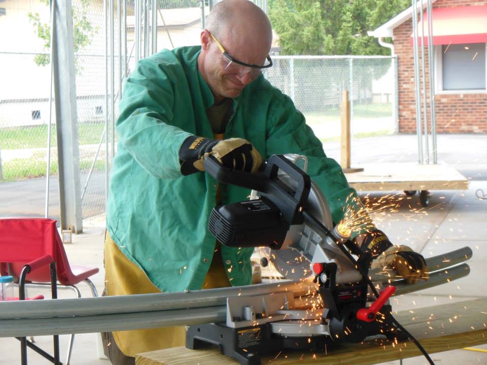
| Here we go bending 1 1/4" pipe for the 2nd roof. The first roof major components are in the background here. As you can see the roof pipe sections consist of 2 pipes bolted together. This is so the roof can be taken apart into 4 sections so it will pack in the truck. So it is important that the pairs of pipe bolted together are bent to exactly the same radius. You could carefully bend each pipe to fit the form or you can use another technique. After bending the first pipe so it fits the form exactly, pull a measuring tape between the inside edges of the finished pipe and note the measurement. And I am not talking about following the arc with the tape, just make a straight line measurement between the ends of the pipe. Then as you are bending the next pipe and you get close to the radius, pull the tape while bending and STOP when you hit the number! I scrapped about $50 worth of pipe before figuring this out. Once you over bend a pipe it is scrap! The lesson here is that the Harbor Freight bender will NOT bend a pipe to the same radius each time with the same setting. Variations in the quality of the steel in the pipe prevent that. Note that to accomplish this requires 3 people manning the bender. One to bend, one to guide the pipe out and straight up so it does not twist and one to measure. |
 |
| Next was building the valances, We needed to build 8 of these and they had to be perfectly square. To do this we built them in a form. It is important that they be perfectly square so when they are bolted to the columns, the columns would stand straight up. The outside dimension had to fit in the form. The different components were cut and checked that they fit the form and adjusted until they did. It was a lot of work but worth it! |
 |
| The tubing notcher was used a lot building the valances because each piece needed to fit pretty precisely to one another. |
 |
| Most of the pipe was pre cut and bent before assembly. |
 |
| Here is another view of the form. The pieces were tack welded in the form and removed for full welding. It is hard to see here but there is a pencil line on the plywood where each piece goes. |
 |
Here is a completed valance! 7 more to go!!! Since they were suppose to be Japanese pagodas I used a Rising Sun theme for the design. These had to be strong. There is a lot of weight up in the air and moving the props on and off the field there will be a lot of bumps and shocks and the valances will bear most of the stress of the pagoda trying to rack back and forth.
Cut the roof sections to length while bolted together to ensure that were even.
|
 |
| Here we are preparing to assemble the 2nd roof. We used the base as a fixture to build the roof. The post in the center is used to temporarily attach the roof sections and is cut to 3 feet in height and screwed to the base in the exact center. The top of the post was trimmed so it is the same dimension as the space between the pipes when assembled. Nothing fancy, just functional. |
 |
| Here we are screwing the roof sections down to the base. The screw locations are exactly where the center of the column will be. |
 |
| Next is to weld temporary bracing on top of the roof sections to hold the sections together and we used 1/2" tubing to do that. A long piece at the bottom and a short piece at the top. We did that so we could remove opposing sections so we could weld in the fascia piece. Since the long fascia piece overlaps the tube we had to remove the adjacent section. We then welded in the fascia and the short upper support section which is a piece of fascia near the top. After welding we used a sawzall to trim off the excess from the top and bottom pieces. Then reinstalled the opposing sections and removed the sections we just finished and repeated the process. After everything was welded up we cut off the temporary bracing. |
 |
| Here is the completed major roof structure bolted back together. |
 |
| Using buckets to simulate the tops of the columns we installed the 1/2" pipe to represent the roof. That is all there is to the roof! |
 |
| We made use of a form to build the columns too. This was the easiest part to build! We made a form by screwing two 2x12's together at 90 degrees (see background) and capped one end with a 12x12 piece of 2 by and made sure it was perfectly square to the form. We had a piece of 3/4" MDF and cut out 2 squares 12" x12" and laid out a 8" diameter circle and divided the circle 8 times and drilled 8 1" holes that are the spacing of the tubes. Then split the fixture in two and used a jig saw to cut 1/2 way throuh the holes so we had a bottom half to hold the bottom 5 pipes and after they were welded in place we pull them and install the top half and finished welding in the last 3 pipes. The columns were made from 3/4" tubing with a 12 x 12 16 gauge steel plate top and bottom that I ordered from Home Depot. |
 |
| You can see the pipe holding fixture just to the left of the white tee shirt. The guy in the blue shirt is holding the top steel plate with another 2 x12 and just put enough pressure to hold the top steel plate in place while tack welding. But the key to success in this component is making sure all 64 pieces ( 8 columns with 8 pieces of pipe each) of pipe were cut to exactly the same length! Again this was done in a made fixture on a miter saw. |
 |
| Finally all of the components are finished and it is time for assembly. We laid the valances on the floor between the columns to set the spacing of the columns and then screwed the columns to the floor. To make sure the lag screws hit the structure we marked the centerline of the support structure underneath the plywood with a chalk line and then drilled and screwed the columns to the floor with 4ea 1 1/2" lag screws on each column. The lags screws did not fall exactly where planned, but close enough! |
 |
| Since the roof fascia dips below the top of the columns the valances had to be lowered from the top of the columns a couple of inches. To calculate this we set the roof on before mounting the valances and measured how far down they needed to be then removed the roof and bolted the valances in place to the inside facing pipe in each column. Since the valances are bolted to a single pipe the box structure was flimsy because the single pipe flexes easily. To strengthen we welded a 7" diameter hoop made from 1/4" round steel to the inside of the column even with the bottom of the valance. This tied all 8 pipes together making it very rigid. I had the hoops made at work but you could just cut pieces of 1/4" steel rod and weld them between each pipe. It would accomplish the same thing. |
 |
| We noticed when we put the roof on the first time that the excess overhanging metal on the plate at the top of the columns interfered with the installation so we rolled the prop over and trimmed off the excess metal. This picture also shows the 7" hoop welded inside the column even with the bottom edge of the valance. |
 |
| And just like that they are complete!. |
 |
| Painting the roof sections gold! |
The painting crew expertly applies a stone look to the floors.
The valances and columns get the red paint!
 |
The pagodas stored in the truck. I wanted you to see how the roof sections nest up to greatly reduce the space they take up. The 2 x 4's in the foreground with the spikes are the poles that will be used to lift the roof on to the columns.
The finished Pagoda!
In Retrospect
Would I do anything different? I think not. It all went off well thanks to the great help of many parents! |


Do you still have these? If so, would you want to sell them?
ReplyDeleteNo these are long gone.
Delete